NOTE: This hobby project is a prototype of an idea and not a finished product. of an idea and not a finished product. Reproduction and use are at your own risk!!!
##General{#General}
On our airfield we like to take off often, de facto exclusively, using a winch. This has a nearly 300HP strong turbo diesel engine and and with a towing distance of about 1200m we reach heights of up to up to 400m with double-seated gliders.
Only the noise of a V8 engine running at full power is too loud for some winch operators. Since during the tow phase, we are in contact with the launch point by telephone, the idea came up to connect a well noise absorbing heaset from aviation to the telephone. However, both the connections and the electrical conditions are different.
Function description
A telephone headset consists of a headset and an Electret microphone. These usually have a small preamplifier in the form of a JFET transistor integrated. To get an AC speech signal out of the microphone, a small bias voltage is needed. For this purpose the phones have a phantom power voltage of between 1.2V and 5V via a series resistor in the order of magnitude of of 1000 Ω, this produces a current of about 1 to 5 mA.
The physical connection is usually a 4P4C, also known as RJ-9 or RJ-10.
A headset in aviation also features relatively good and noise-absorbing headphone cups and a microphone. Said mic seems to contain a somewhat more complex circuitry, because it needs about 9V and a series resistor of 4 kΩ to operate. Leading to a bias current of about 3 mA.
This extra current and voltage, i.e. power, must come from somewhere, now the potentials of the microphone most likely cannot be directly connected to the strong and powerful starter battery of the winch. A galvanic isolation would be nice, which is easy to realize using an independent battery.
For comparison, a 9V block has a capacity of approx. 450 mAh, so at 3 mA an operating time of about 150h can be expected.
This does not sound bad at first, but one could make this switchable. But practice shows that all things that have to be switched on/off manually are often are often forgotten. So it is then very likely that such a headset adapter with manual activation is regularly either switched off when trying to make a phone call or remains switched on when not in use and then the battery would be totally drained just in time for use.
So only an automated solution is an option for the everyday life of the glider pilot.
Electronics

The circuit is a relatively simple analog circuit without much magic. In the schematic, the individual function groups are highlighted.
In the initial state, R1 pulls the gate of Q2 to positive potential. A P-channel MOSFET transistor like Q2 blocks in this case as long as the difference from gate to source is greater than approx. -2V.
The detection if the headset should be supplied with power or not is done by Q1. If the phone wants to supply the actual headset with power, it will output about 1.2V DC as phantom power. This is sufficient to supply a base current of about 600 uA into the transistor Q1.
This then becomes conductive and pulls R1 to ground, leading to an additional battey load of current of about 90 uA which flows out of the battery via R1, that, compared to the consumption of the headset, is negligible. Via R3 the aviation headset gets its phantom power.
C1 now couples the AC voltage from the headset microphone back to the telephone’s microphone input.
If the phone is hung up, it switches off the power supply of the supposed headset. Thus no more current flows into the base of Q1 and R1 pulls the gate of Q2 to the positive rail which then stops conductng and thus terminates the current flow to the actual headset.
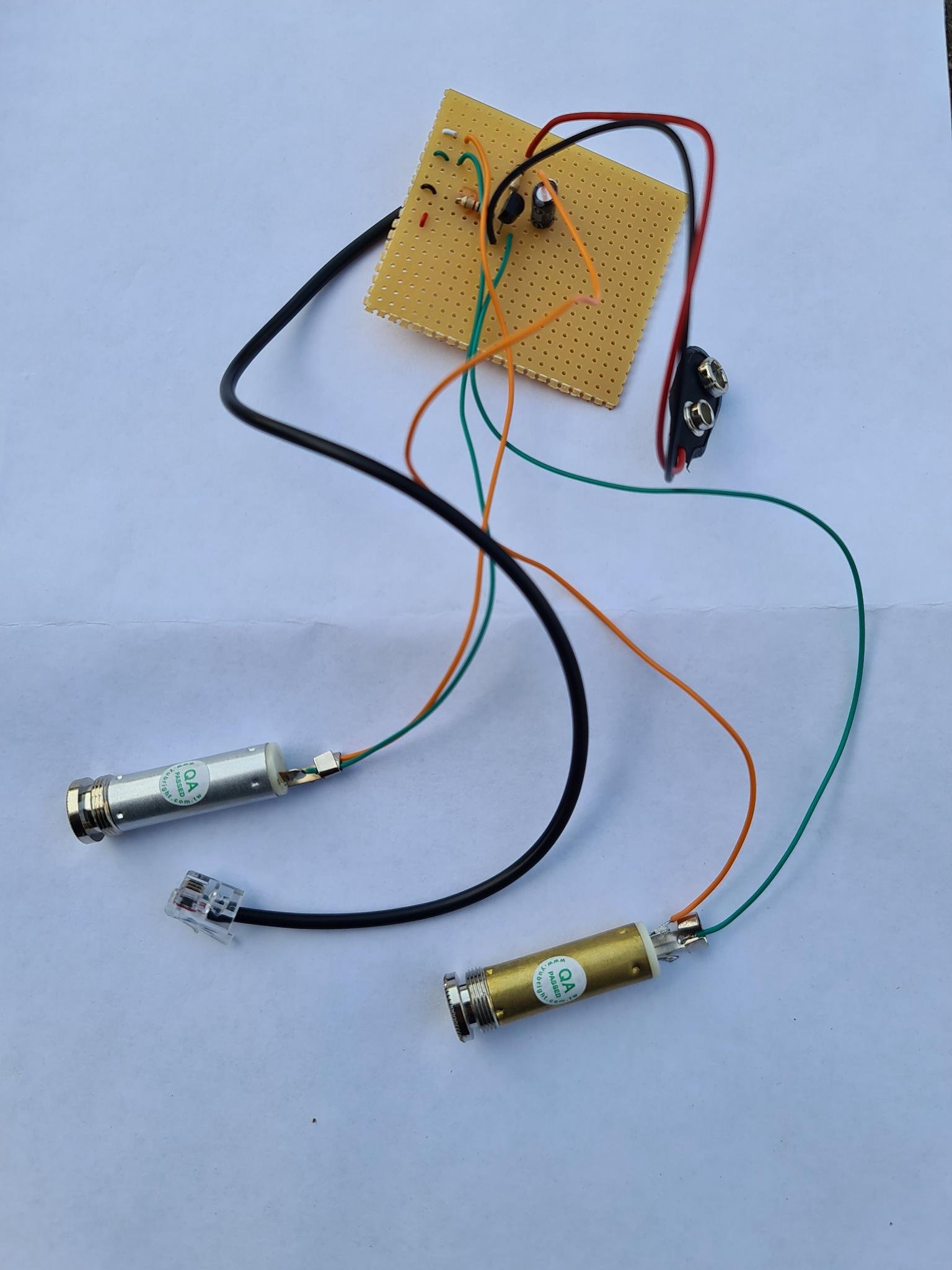
##Mechanical construction{#mechanics}