Here is the setup of an electronic door access control system for clubs and also private use.
WARNING: This hobby project is a prototype of an idea and not a finished product. Replication and usage are at your own risk!!!
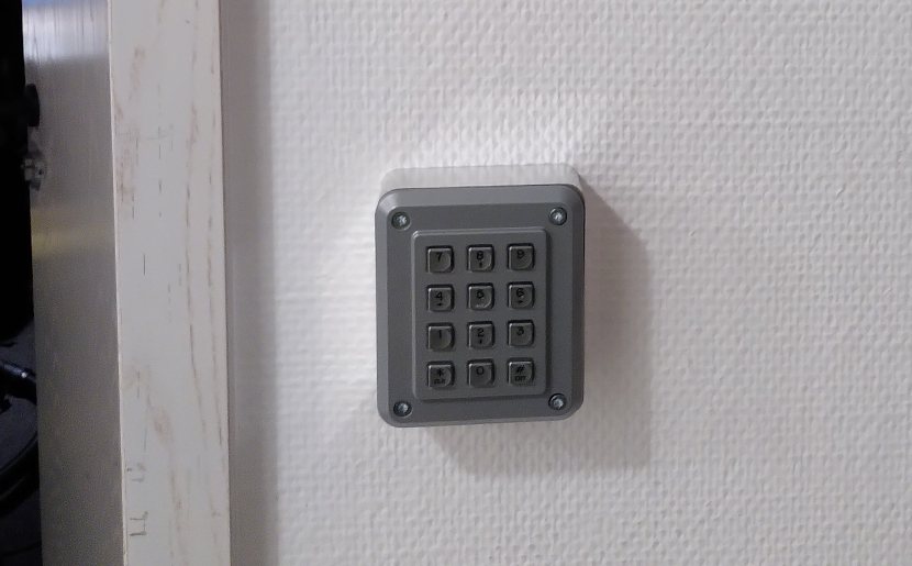
Pinpad near the hacker space door
General Information
In shared spaces, especially those used by multiple groups such as clubs, controlling access can be challenging. Particularly when external parties need to open the outer doors during events, traditional methods like keys and lock systems often reach their limits.
If one wants to make it more “intelligent,” they may find themselves locked into proprietary ecosystems. For instance, RFID access tokens can be expensive and are usually limited to the provider’s system. At best, an app on a smartphone is available. But what if the provider discontinues the product and these devices become obsolete electronic scrap?
This is neither sustainable nor financially viable. We can do better, right?
The project started at our hackerspace https://www.mudbyte.de, so all the components presented here were developed in common.
The system is aplty called zuul, referring to the gatekeeper daemon in a popular science fiction universe.
Function Description

The basic principle of this system is two-factor authentication. This is implemented using a printed code (QR or barcode) and a PIN.
For short-term access data, such as for events, a pure PIN with an expiration time can also be used.
This setup consists of four components running on two different hardware platforms:
Next to the door, there is a PIN pad with built-in combined QR and barcode scanner.
Attached to the door is a stepper motor that actuates the lock cylinder. This motor is connected via an Arduino-based board and a suitable stepper motor driver.
These two devices are connected over USB or RS485 to a Raspberry Pi or similar micro-computer.
On the software level, there are two largely independent components: The device driver enumerates all serial devices connected via USB and attempts to communicate with them. It then groups these devices by name and function, allowing multiple doors to be controlled from one computer. This component only handles communication with the door devices; access decisions are delegated through HTTP(S) to another component, which can be easily replaced.
The backend and management software checks for valid access rights (in terms of time and content) and logs successful closing actions.
The PIN Pad
Description
The PIN pad consists mechanically of a vandalism-resistant keyboard in an aluminum casing. Inside the casing is also a QR/barcode scanner module.
It turned out that the pin layouts of different Chinese manufacturers varied significantly, even though the connectors were mechanically compatible. So, power supply and data lines were swapped, which would have led to damages in the respective modules when swapping them between manufacturers. Additionally, the screw holes were ever so slightly offset, so the threaded holes had to be strategically placed to accommodate both known variants.

Hardware
Parts list:
- PIN keyboard: Storm Interface 1K120101
- Barcode scanner: Waveshare Barcode Scanner Module, SEENGREAT USB Barcode Scanner Module
- Aluminum casing: Custom-machined, design in the git repository
- Arduino Nano
- B-Micro USB cable, with 90 degree bend
- Piezo buzzer for audio feedback

Keypad schematic
The Arduino Nano is mounted piggybacked on the keyboard module, with the connections to the barcode scanner also soldered directly onto the Arduino. This ensures a solid connection between keyboard and the Arduino.
If the casing is 3D-printed, the Arduino can be clipped into place in the designated slots.
For RS485 communication instead of USB, this module must also fit inside the casing. However, this should not pose any problems.
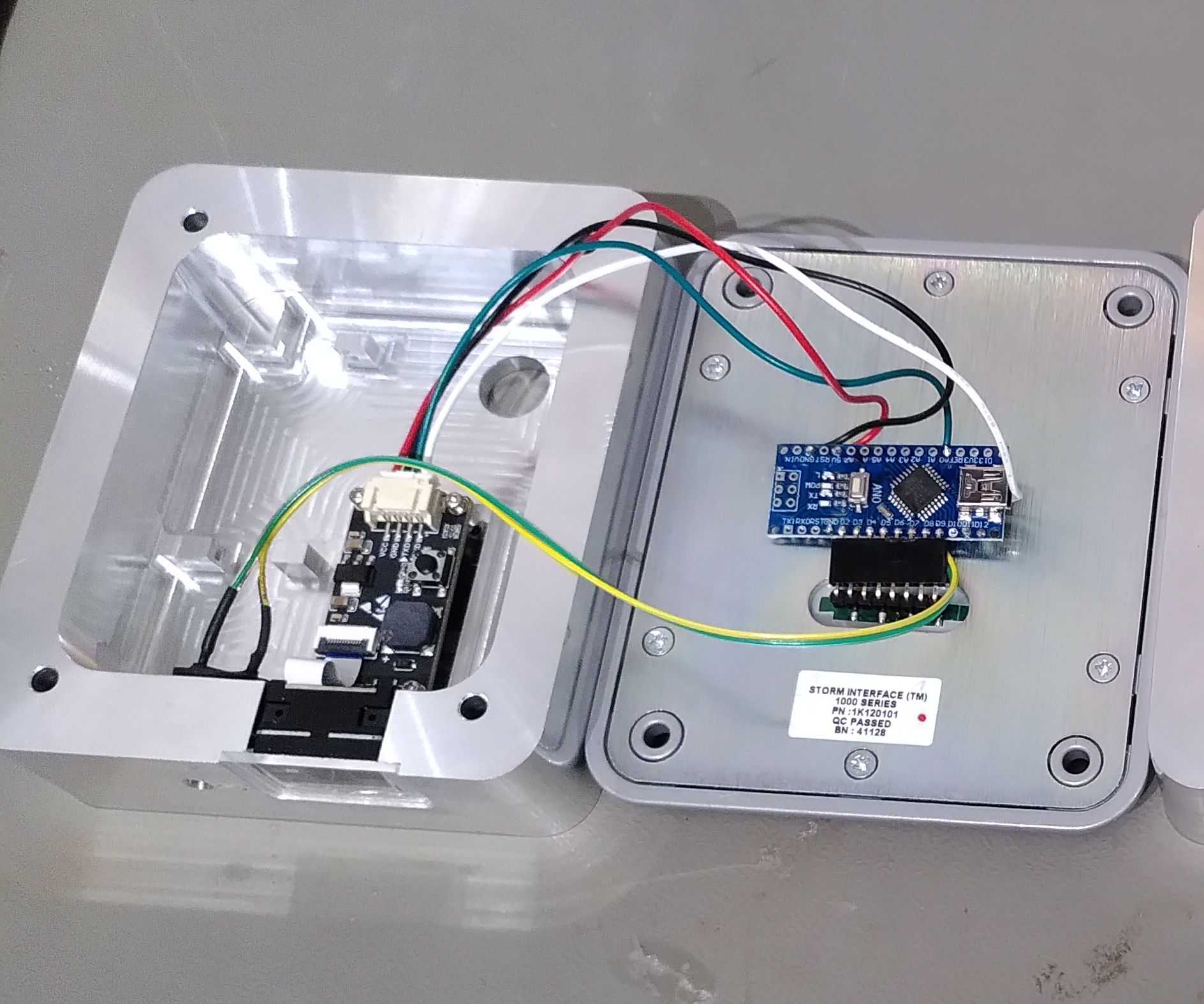
Assembly of components
Software
All Arduino-based devices share a common software, simplifying future field updates.
The Lock Mechanism
Description
Actuating and interfacing a traditional lock cylinder often proves more challenging than expected. If one wants to use a normal key for locking, it is necessary that the actuation mechanism is sufficiently easy to turn when not working so that is not overly stiff for the key to turn and does not break the key by shearing forces.

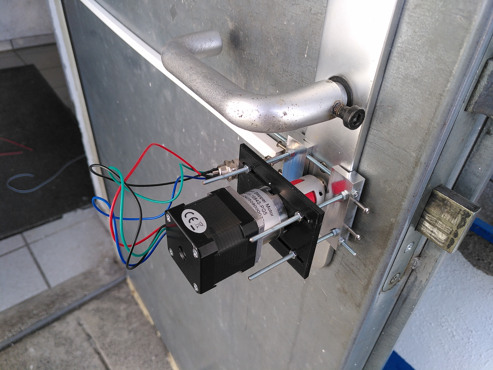
Therefore, a stepper motor (5) was used. In the first installation at our hackerspace, a NEMA-15 stepper motor from a 3D printer proved sufficient. The new building’s lock cylinder turned out to be very stubborn and required a gear reduction mechanism (4).
To connect the motor to the lock cylinder, cylinders with knobs on one side have proven effective because they usually allow for removable knobs. Underneath you find as shaft with diameters ranging between 8mm and 10mm. However, there seems to be no standardization here as well, so either a flexible coupling that fits both variants exactly or one must be custom-machined on a lathe.
The mechanical connection of the motor to the door also presents a challenge. It appears that every door escutcheon plate manufacturer has its own idea about how these should be attached to the door. So far, a special adapter in 3D-printed form had to be manufactured for each installation (6).
Universal escutcheon plate grip at the airfield
Recently, there is also a “universal” holder for traditional straight escutcheon plates, which unfortunately did not fit the so-called rosetta style on the new locations building’s door.
Electronics
The stepper motor is controlled via a SilentStepStick connected to an Arduino. A custom PCB was designed by a club colleague and is already in its second iteration of use. At the airport, a similar PCB from an enterprise for production-quality control of material flow heaters was used.
Software
When set to “Door Mode” (door actuation), the Arduino can be configured to specify the number of steps required for reliable locking. The motor runs a fixed number of steps both to open and close the door, which is measured so that it stops magnetically (“stalls”) in the final position. This ensures complete closure.
Device Driver and Protocols

Communication between components
Device Protocol
The protocol between devices and the software on the control computer is kept as simple as possible. It consists of ASCII telegrams that are terminated with a newline (\n).
Each field is separated by a pipe (|) and is structured as follows:
<name>|<device_type>|<message_type>|<data>
The exact protocol and options are more thoroughly explained in the firmware code repository.
During discussions on communication, it was noted that there are two device types: DOOR and KEYPAD. Each of these is assigned a name, for example “inside”. The driver then collects these devices and assigns them to multiple locations based on their names. These form “gates”, consisting of a PIN pad and a door actuator, which can be identified by their name.
This is done via PING commands that generate a PONG response from the device. Thus, the driver discovers connected devices. All recognized USB-serial devices (in Linux /dev/ttyUSB* and /dev/ttyACM*) are enumerated regularly. This means that even the loss of a connection is tolerated, and upon reconnection, the old device handler will be found reliably, even if it has been reassigned. Old instances are appropriately discarded.
If “0000” is entered four times followed by “#”, the door will be locked.
Web Service/Backend
If a different PIN from “0000” is entered and confirmed using the “#” key or by scanning a QR or barcode, this is recognized by the driver software. It then forms a hash from the PIN and optionally scanned code using the scrypt algorithm. This requests the backend via HTTP(S) at configured URLs following the schema http://<hostname>/keymaster/verify/<gate>/<hash>.
If an HTTP status code 200 is returned, an opening command is sent to the door actuator board, and a tone sequence for positive confirmation is played.
Any other status code results in a rejection tone being played, and the door remains closed.
This makes the backend completely flexible between a web application developed using a web framework and a primitive web server that only finds small files on the file system named randomly like a hash or not at all. So the backend can be easily replaced or adapted.
Multi-Backend Operation
Naturally, a single server can also manage multiple doors. Given the use case in our hackerspace which is located in a building used by several clubs/coworking spaces etc., another option was implemented to allow a CommTask to query multiple web services sequentially. This involves querying each service step-by-step, such as the one for our hackerspace, then the landlord’s, until the token is either recognized as valid or no backend remains to be queried.
This allows multi-level authentication without having to copy data between instances.

Communication between components
Backend/Management Interface
This subsystem was implemented in the reference implementation using Python and the Django web framework.
With this, a simple creation of an admin interface under consideration of modern attack vectors such as CSRF was possible. Instead of implementing a larger custom web solution, the “admin” interface provided by Django is used for token management tasks.
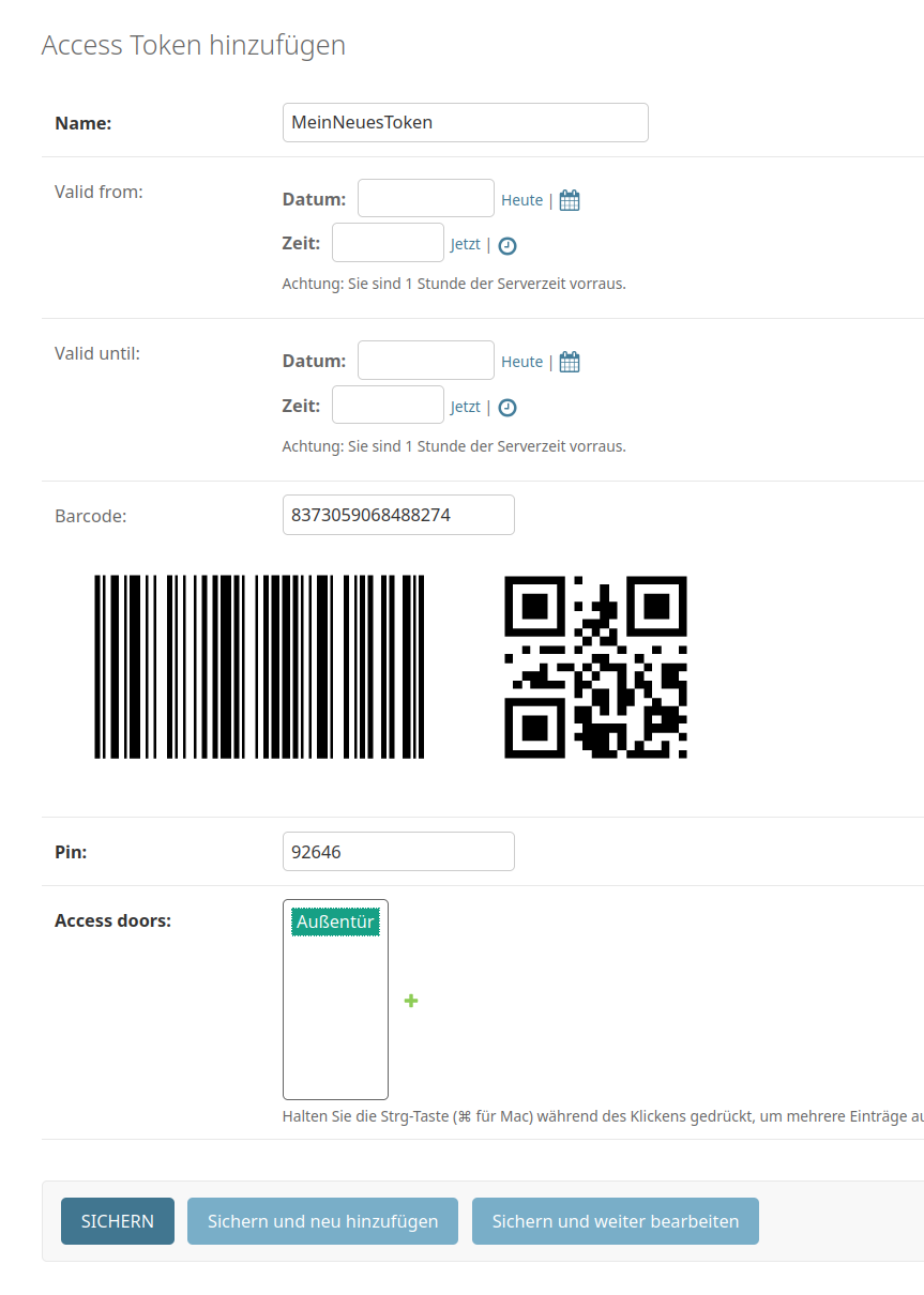
Creating a token in the frontend
All other tokens can optionally be assigned a validity time frame as well. These time frames are always an from-to time range, allowing for tokens that become valid in the future. This is particularly useful for events where codes can be distributed beforehand and become active during the event period.
In the system, only the hashes (very hard to reverse-engineer fingerprints), PINs, and QR/barcode data are stored. Thus, it’s not possible from the frontend to re-create or read out existing codes, which enhances the security of these codes.
When creating a token, it can also be printed directly in “print mode.” A special HTML view shows this in print format. The code and PIN are printed on one page each. The codes are printed in credit card format, making them easy to carry in a wallet. Integration into modern Passbook/Wallet apps on smartphones is planned as well.
Source code
These are the repositories containing the different components of the system:
The door controllers schematics and layout are not available at this time, as the original author has
not yet been contacted if a release would be ok. You can find the Arduino pin configuration
in zuul_device_firmware.ino. It should not be too hard whipping something up.